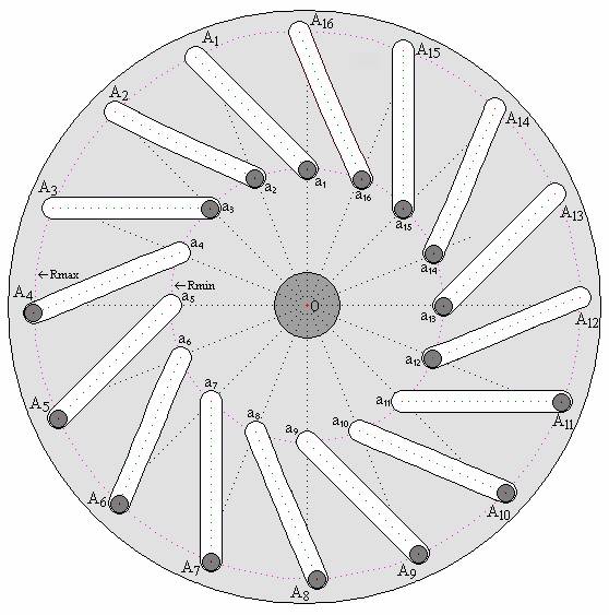
Fig. 2
Let us consider again Figure 2, shown in the main text.
Rmin — radius of the circumference, along which are uniformly distributed centers of gravity of movable loads in the state of their minimum distance from the axis of rotation of the disk;
O — center of the disk (the axis of rotation of the disk);
Rmax — radius of the circumference, along which are uniformly distributed centers of gravity of the movable loads in the state of their maximum distance from the axis of rotation of the disk (Rmax = kRmin, where k – coefficient that indicates the degree of exceeding the length Rmax with respect to Rmin);
β°(Rmin) — angular distance (angle) between the radiuses Rmin, outgoing from the center of disk (point “O”) and ingoing in the centers of gravity of two any adjacent loads;
β°(Rmax) — angular distance (angle) between the radiuses Rmax, outgoing from the center of disk (point “O”) and ingoing in the centers of gravity of two any adjacent loads;
Fg — force of gravity, acting on any movable load;
Mg — torque, generated by a load under the action of only gravitational force;
∑Mg — total torque, produced by all the movable loads under the influence of gravity;
n — total amount of loads.
We supplement the initial data by introducing Cartesian coordinates, the origin of which is the point “O” (Fig. 2).
The torque generated by each load is equal to the product of the gravitational force Fg on the lever arm (d), whose length is determined by the position of the centre gravity of the load relative to the axis of rotation of the disk (point “O” in Fig. 2). The resultant torque is the sum of the torques generated by each load, taking into account their signs. For calculation of the resulting torque (the net torque) is required to calculate the lengths of the lever arms of all loads which are shown in Fig. 2. To do this, first of all, we must calculate the length of the lever arm d, i.e. the coordinate X of the center of gravity of any one load, placed on the circle Rmin, and of one - on the circle Rmax. The directions of the radii, corresponding to the centres of gravity of two loads, which were originally selected, we take as initial. The calculation of the lengths of the lever arms all other loads we make, taking into account the angles of displacement of the appropriate radiuses (Rmin/Rmax) relative to the initial directions. The displacement should be done consistently, taking into account that the angles between the directions of any adjacent radiuses are equal to β° = 22.5°.
Consider the location of the centers of gravity loads shown in Fig. 2. The point a1 is convenient to take as the starting point for calculation the lengths of the lever arms of torques generated by the loads, whose centers of gravities are from the rotational axis at the distance Rmin, and the point A4 - for the loads at maximum distance from the axis of rotation (at the distance Rmax).
The center of gravity of the load a1 is on the axis Y, passing through the axis of rotation of the disk (through the point “O” ), that corresponds equality to zero for the length of the lever arm (da1) of this load (da1 = Rmin·cos90° = 0).
Calculating the length of the lever arm d�4, i.e. the coordinate X for the center of gravity of the load A4, performed in the following order:
Y(a3) = Rmin·sin45° = 0.701Rmin.
Y(A3) = 0.701Rmin.
y2 = R2.
By solving this equation for the coordinate X(A3), we find:
X(A3) = √( R2max − Y2(A3)) = √(4R2min − 0.7072R2min) = Rmin√(4 − 0.5) = 1.871Rmin.
∠φ°(A3) = arcos(X(A3)/Rmax>) = arcos(1.871Rmin/Rmax ) = arccos(1.871/2) = 20.69°.
∠φ°(A4) = ∠β°(Rmax) − ∠φ°(A3) = 22.5° − 20.69° = 1.81°.
d�4 = 2Rmin· cos1.81° = + 1.999Rmin.
The calculation of the net torque produced of all 16 loads was made for the six fixed states of rotation of the disk. The initial state corresponds to Fig. 2. The remaining five states correspond to the results of a consistent rotation of the disk counterclockwise at angles that are listed below:
The results of the calculation of the torques provided by each from the 16 loads at these turnings of the disk, and the net torques, corresponding to these states, are shown in Tables 1 and 2. In Table 3 is summarized the results of calculations to assess the behavior of the net torque in the process of turning the disk in the range 0° – 22.5°. Because of the fact that the inclined paths for displacement of the loads are distributed equally and symmetrically about the axis of rotation of disk, the behaviour of the net torque should be repeated in each sector of the turning disk on angle 22.5°.
| State of the disk corresponds to Fig. 2 |
The disk has been rotated counter-clockwise on the angle β°(Rmin)× 1/8 = 22.5°×1/8 = 2.8125° |
The disk has been rotated counter-clockwise on the angle β°(Rmin)× 1/4 = 22.5°× 1/4 = 5.625° | |||
|---|---|---|---|---|---|
| Load | Mg | Load | Mg | Load | Mg |
| a1 | FgRmincos270° = 0 | a1 | FgRmincos87.1875° = +0.049FgRmin | ||
| The disk has been rotated counter-clockwise on the angle β°(Rmin)×½ = 22.5°×½ = 11.25° |
The disk has been rotated counter-clockwise on the angle β°(Rmin)× 3/4 = 22.5°×3/4 = 16.875° |
The disk has been rotated counter-clockwise on the angle β°(Rmin)× 7/8 = 22.5°× 7/8 = 19.6875° | |||
|---|---|---|---|---|---|
| Load | Mg | Load | Mg | Load | Mg |
| a1 | FgRmincos281.25° = +0.195FgRmin | a1 | FgRmincos73.125° = +0.290FgRmin | a1 | FgRmincos70.3125° = +0.337FgRmin |
| a2 | FgRmincos303.75° = +0.556FgRmin | a2 | FgRmincos50.625° = +0.634FgRmin | a2 | FgRmincos47.8125° = +0.672FgRmin |
| �3 | Fg2Rmincos350.56° = +1.971FgRmin | �3 | Fg2Rmincos3.815° = +1.996FgRmin | �3 | Fg2Rmincos1.0025° = +2.000FgRmin |
| �4 | Fg2Rmincos13.06° = +1.948FgRmin | �4 | Fg2Rmincos18.685° = +1.895FgRmin | �4 | Fg2Rmincos21.4975° = +1.861FgRmin |
| �5 | Fg2Rmincos35.56° = +1.627FgRmin | �5 | Fg2Rmincos41.185° = +1.505FgRmin | �5 | Fg2Rmincos43.9975° = +1.439FgRmin |
| �6 | Fg2Rmincos58.06° = +1.058FgRmin | <�6 | Fg2Rmincos63.685° = +0.887FgRmin | �6 | Fg2Rmincos66.4975° = +0.798FgRmin |
| �7 | Fg2Rmincos80.56° = +0.328FgRmin | �7 | Fg2Rmincos86.185° = +0.133FgRmin | �7 | Fg2Rmincos88.9975° = +0.035FgRmin |
| �8 | Fg2Rmincos103.06° = −0.452FgRmin | �8 | Fg2Rmincos71.315° = −0.641FgRmin | �8 | Fg2Rmincos68.5025° = −0.733FgRmin |
| �9 | Fg2Rmincos125.56° = −1.163FgRmin | �9 | Fg2Rmincos48.815° = −1.317FgRmin | �9 | Fg2Rmincos46.0025° = −1.389FgRmin |
| �10 | Fg2Rmincos148.06° = −1.697FgRmin | �10 | Fg2Rmincos26.315° = −1.793FgRmin | �10 | Fg2Rmincos23.5025° = −1.834FgRmin |
| a11 | FgRmincos146.25° = −0.831FgRmin | a11 | FgRmincos28.125° = −0.882FgRmin | a11 | FgRmincos25.3125° = −0.904FgRmin |
| a12 | FgRmincos168.75° = −0.981FgRmin | a12 | FgRmincos5.625° = −0.995FgRmin | a12 | FgRmincos2.8125° = −0.999FgRmin |
| a13 | FgRmincos191.25° = −0.981FgRmin | a13 | FgRmincos16.875° = −0.957FgRmin | a13 | FgRmincos19.6875° = −0.942FgRmin |
| a14 | FgRmincos213.75° = −0.831FgRmin | a14 | FgRmincos39.375° = −0.773FgRmin | a14 | FgRmincos42.1875° = −0.741FgRmin |
| a15 | FgRmincos236.25° = −0.556FgRmin | a15 | FgRmincos61.875° = −0.471FgRmin | a15 | FgRmincos64.6875° = −0.428FgRmin |
| a16 | FgRmincos258.75° = −0.195FgRmin | a16 | FgRmincos84.375° = −0.098FgRmin | a16 | FgRmincos87.1875° = −0.049FgRmin |
|
∑Mg = (+7.683
−7.687)FgRmin =
−0.004FgRmin |
∑Mg = (+7.340
−7.927)FgRmin =
−0.587FgRmin |
∑Mg = (+7.142
−8.019)FgRmin =
−0.877FgRmin |
|||
| � of the source table |
The angle of rotation disk counter-clockwise relative to state of Fig. 2 |
∑Mg |
|---|---|---|
| 1 | State of the disk corresponds to Fig. 2 |
∑Mg = (+6.988 −8.153)FgRmin = −1.165FgRmin |
| 1 | β°(Rmin)× 1/8 = 22.5°×1/8 = 2.8125° | ∑Mg = (+8.063 −7.192)FgRmin = +0.871FgRmin |
| 1 | β°(Rmin)× 1/4 = 22.5°× 1/4 = 5.625° | ∑Mg = (+7.957 −7.295)FgRmin = +0.665FgRmin |
| 2 | β°(Rmin)× 1/2 = 22.5°×1/2 = 11.25° | ∑Mg = (+7.683 −7.687)FgRmin = −0.004FgRmin |
| 2 | β°(Rmin)× 3/4 = 22.5°×3/4 = 16.875° | ∑Mg = (+7.340 −7.927)FgRmin = −0.587FgRmin |
| 2 | β°(Rmin)× 7/8 = 22.5°× 7/8 = 19.6875° | ∑Mg = (+7.142 −8.019)FgRmin = −0.877FgRmin |
The results of calculations show the following.
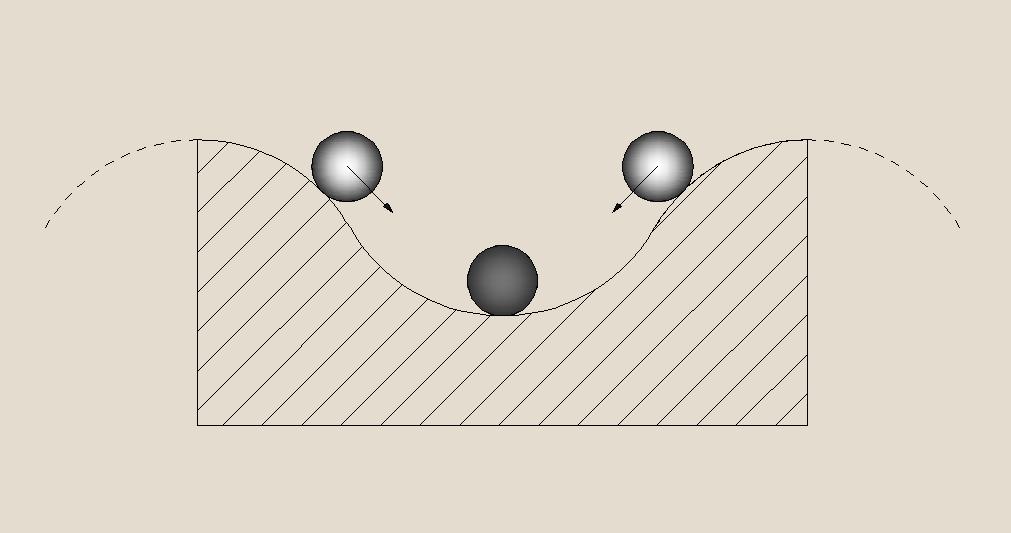
The rotation of the disk is possible only when another force acts on it. We call it the "external" force (external with respect to gravity). After the cessation of such exposure the disk must to stop. And it should stop in position corresponding to the turning, regarding the state shown in Fig. 2, by the angle β°(Rmin)×1/2 = 22.5°×1/2 = 11.25°. And this is entirely consistent with the feature which determined by potential nature of the gravitational field, which consists in the fact that work on the movement of any physical object in a closed path is zero. In the system, corresponding to Fig. 2, the trajectory of the center of gravity of each load - closed. This device, like any other, like it, after the cessation of the external force action, inevitably comes to a state of stable equilibrium[32]. At this, in the device according to Fig. 2, there are 16 states in which it is possible to ensure of stable equilibrium.
Such a state can be compared with the state of the ball what is shown in the Figure 15.
The results of calculation in a general form of the net torque allows us to select the magnitude and direction of the optimal annex of external force action to ensure the long lasting rotation of the disk with partial use of the kinetic energy of the gravitational field.
The Figures 2 and 3 of the main text clearly show and the results of calculation (that are listed in Tables 1-3) numerically confirm in the following:
*
* * *
It is easy to see, that if by using an external force will be possible to counteract the gravitational impact on the loads, moving in the sector A8 – O – A11 (Fig. 2), the effect of gravity on this section of the trajectory movement of loads will be reduced to zero. Equilibrium in such a state of the system will be broken. And during the time of action of this external force the resultant rotating effort will be determined by the total torque created by the loads specified in paragraph 1. The disk will be able rotate. At the same time a prerequisite for ensuring the possibility of rotation is that the magnitude of the resulting torque must ensure overcoming the total resistance to the rotation produced by useful load on the motor shaft, friction, heating, and other possible impacts impeding to rotation.
*
* * *
Of course, the bulky calculation, resulted above, does not can add anything new to the fundamental concept of the physics - to the Law of Conservation of Energy, as well as to the feature of a potential character of gravity field of the Earth, concerning the equality to zero of the work of the force acting on a body, moving along the closed trajectory. However, this calculation allows understand, where the most appropriate to apply external force effort, in order to provide in such a system the rotation with partial use of the kinetic energy of the gravitational field of the Earth. The results of calculation "in general form" also allow to obtain numerical estimates of the contribution of each movable load in creating of a common torque by substituting into received symbolic expressions the real numeric values of weight of the movable loads and the values of the corresponding lever arms of rotation.
Successful utilizations of the kinetic energy of the Earth's gravity jointly with the influence of other forces of nature are used by people for a long time. Suffice it to recall, that hydroelectric power plants work by using the kinetic energy of water falling from great heights. But the rise of the water to great heights occurs due to the influence of other forces of nature. Or skier, sliding down to his great satisfaction from the mountains due to the influence of gravity, is forced to use the energy of his muscular effort to rise on mountain.
This page was last modified on 18 September 2014